What Was Published
On August 25, 2026, Lam Research's Semiverse Solutions group published a study by Swapnil Kailash More applying SEMulator3D virtual fabrication with integrated stress modeling to gate-all-around (GAA) nanosheet transistors. The question: how much does mechanical stress vary between the stacked channels of a single GAA device, and which process parameters drive that variation.
The answer is process-side, not layout-side. The three parameters the study identifies are individual silicon channel thickness, fin width, and the fin lateral etch ratio — the taper introduced during fin patterning. Two of those three are set on an etch tool.
Why Stress Uniformity Decides How a GAA Device Behaves
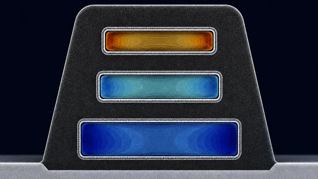
A GAA device is a vertical stack of isolated silicon channels wrapped by a common gate. Stress in those channels reshapes the silicon band structure and therefore carrier mobility, saturation current, off-state current, and threshold voltage. In the ideal case every channel in the stack sees identical stress and behaves identically.
In practice they do not. Lam's framing of the consequence is the part worth reading twice: the highest-stressed channel has the best mobility and carries a disproportionate share of the current, and a high-strain, low-Vt channel can dominate off-state leakage for the whole device even when the other channels are well controlled. A stack that looks uniform in the layout can turn on and leak like something else entirely.
The stress itself comes from lattice mismatch with the epitaxially grown source/drain. For the pFET the source/drain material has a slightly larger lattice constant than silicon; for the nFET, slightly smaller. During replacement-metal-gate (RMG) processing the channels become freestanding and those stressors relax — compressive source/drain expands and pushes the pFET channels into compression, tensile source/drain contracts and pulls the nFET channels into tension. The model solves stress at every major step change: the epitaxial Si/SiGe stack, fin patterning, the gate module, source/drain growth, and RMG.
The Numbers: Top Channel Thickness Dominates
Lam ran a design of experiments varying the three individual channel thicknesses and the fin width, then extracted average longitudinal stress (Sigma_yy) along a vertical cut through the stack. The plot shows three distinct stress peaks — one per nanosheet — compressive for the pFET, tensile for the nFET, and visibly unequal in magnitude.
The asymmetry between device types is large. Reported pFET stress difference across the stack stays under 200 MPa. The nFET reaches 400 to 800 MPa over the same DOE space.
The strongest single lever is the thickness of the topmost channel. As Channel 3 thickness increases from 4 nm to 7 nm, the stress-difference contours move from the high end of the range to the low end. Lam's conclusion is that the top channel needs to be slightly thicker than the ones below it to equalize stress across the stack — a counterintuitive result that would be difficult to reach from geometry reasoning alone.
Fin Lateral Etch Ratio: Where the Etcher Enters the Picture
Fin width on its own turns out to matter only conditionally — and the condition is set by the etch. The fin lateral etch ratio controls fin taper, which determines how much channel width is lost above the shallow trench isolation elevation. At low taper, the channels in the stack are close to the same width. At high taper, the top channel ends up significantly narrower than the bottom one.
The study reports that at lateral etch ratios of 0.05 and 0.075, the stress-difference contours barely move as fin width is reduced. At a ratio of 0.1 — a larger taper — fin width starts to matter substantially. The worst case reported is a narrow fin of 25 to 26 nm combined with a thin top channel of 4 to 5 nm, which produces an nFET stress difference of 900 MPa. Holding fin width at 25 nm and increasing Channel 3 thickness from 4 nm to 7 nm brings that back to roughly 500 MPa. The same interaction exists on the pFET but is weaker, and only appears under excessive lateral etch.
Stated as a process-control result: sidewall taper during fin patterning is not merely a CD-uniformity concern at advanced nodes. It propagates through the channel cross-section into stress, and from stress into Vt spread and leakage. Controlling it is the classic problem of decoupling ion energy from ion density so that directionality can be dialed independently of etch rate — the design intent behind ICP-RIE etching, and the reason profile control gets treated as a first-class process parameter rather than a byproduct.
What the Study Does Not Show
This is a simulation study published on a tool vendor's blog. There is no silicon data, no measured Vt distribution, and no yield result. The absolute stress values depend on the assumed material set and process sequence in the model. Its value is directional — the ranking of which knobs matter and the sign of their effect — not the specific megapascal figures.
Worth noting for context: Lam broke ground on a 120,000-square-foot Oregon lab in Tualatin on August 26, expanding cleanroom space there by more than 50% and adding capability specifically for advanced deposition and etch process development, materials science, and hardware validation. It is the first site in a stated $3 billion, five-year global lab expansion announced August 13. Simulation of this kind is what happens before wafers get run; the lab investment is what happens after.
NineScrolls Niche Angle
For plasma processing: The direct takeaway is that fin sidewall taper carries a device-level penalty that scales nonlinearly. At a lateral etch ratio of 0.075 the process is largely insensitive to fin width; at 0.1 it is not. That is a narrow window, and holding it requires independent control of ion directionality and etch rate. If you are specifying or qualifying an etch process where profile angle is the critical output, the regime distinctions in PE vs. RIE vs. ICP-RIE plasma etching are the right starting point, and the mechanism by which ion bombardment and chemical etching combine to set an anisotropic profile is covered in our reactive ion etching guide.
For thin-film deposition: Channel thickness in this study is set by the epitaxial Si/SiGe superlattice, and the DOE says a 3 nm difference in the top layer moves stress uniformity by hundreds of MPa. Layer-thickness control in the stack is therefore a device-performance parameter, not a nominal spec. Downstream, the RMG module deposits gate dielectric and metal into a freestanding, fully wrapped geometry where conformality is the entire requirement — the sort of high-aspect, all-around coverage problem addressed in our ALD guide.
For the equipment supply chain: Virtual fabrication is increasingly where process windows are argued before a tool is bought. For research labs and smaller fabs that cannot run a full DOE in silicon, the practical version of this is knowing which parameters on a given etch or deposition platform are independently controllable — bias power separate from source power, taper separate from rate — because that determines whether a modeled window can actually be hit on hardware. Chemical versus physical removal behaves very differently in that respect, a comparison we lay out in RIE vs. ion milling.
Sources
- Virtual Fabrication Meets Stress Physics: Solving GAA Channel Non-Uniformity — Lam Research, August 25, 2026
- Lam Research Breaks Ground on New Oregon Lab — Lam Research, August 26, 2026
- Lam Research Announces Plans to Invest More than $3B to Expand Global Lab Network — Lam Research, August 13, 2026
- SEMulator3D — Lam Research product page