
Target Readers: Lab managers, equipment engineers, process technicians, and facility maintenance teams responsible for keeping plasma cleaning systems in reliable working condition. Whether you operate a compact benchtop plasma cleaner or a large-format production system, these maintenance practices will extend equipment life and ensure consistent process results.
TL;DR
- Plasma cleaners require regular maintenance across three pillars: vacuum environment, energy source, and process medium (chamber, electrodes, tray racks).
- Chamber cleaning should be performed weekly using lint-free wipes with IPA, followed by a 10-minute O₂ plasma self-clean cycle.
- Electrodes and tray racks accumulate oxide layers and hydrocarbon residue that degrade process stability — refurbish them semi-annually with a NaOH/H₂SO₄ chemical cleaning process.
- A structured preventive maintenance schedule (daily → annual) is the most effective way to prevent unplanned downtime and maintain etch/clean uniformity.
- Never use abrasive mechanical methods on electrodes — chemical cleaning preserves surface finish and extends electrode life.
Why Plasma Cleaner Maintenance Matters
Plasma cleaning systems operate in demanding conditions: low-pressure vacuum environments, high-energy RF fields, and reactive gas chemistries. Over time, these conditions cause predictable wear patterns — contaminant buildup on chamber walls, oxide layer formation on electrodes, seal degradation, and gradual drift in vacuum and RF performance.
Without systematic maintenance, these effects compound silently. Process results may appear acceptable for weeks before a sudden shift in cleaning uniformity, adhesion test failures, or unexplained particle contamination reveals the underlying degradation. By that point, the equipment may require costly emergency repairs and extended downtime.
A well-executed preventive maintenance program delivers measurable benefits:
- Consistent process results — stable cleaning performance run after run
- Extended equipment life — electrodes, seals, and vacuum components last significantly longer with regular care
- Reduced unplanned downtime — catching wear early prevents catastrophic failures
- Lower cost of ownership — preventive care is always cheaper than reactive repair
- Regulatory compliance — documented maintenance records satisfy audit requirements in regulated environments (semiconductor, medical device, aerospace)
The Three Pillars of Plasma System Maintenance
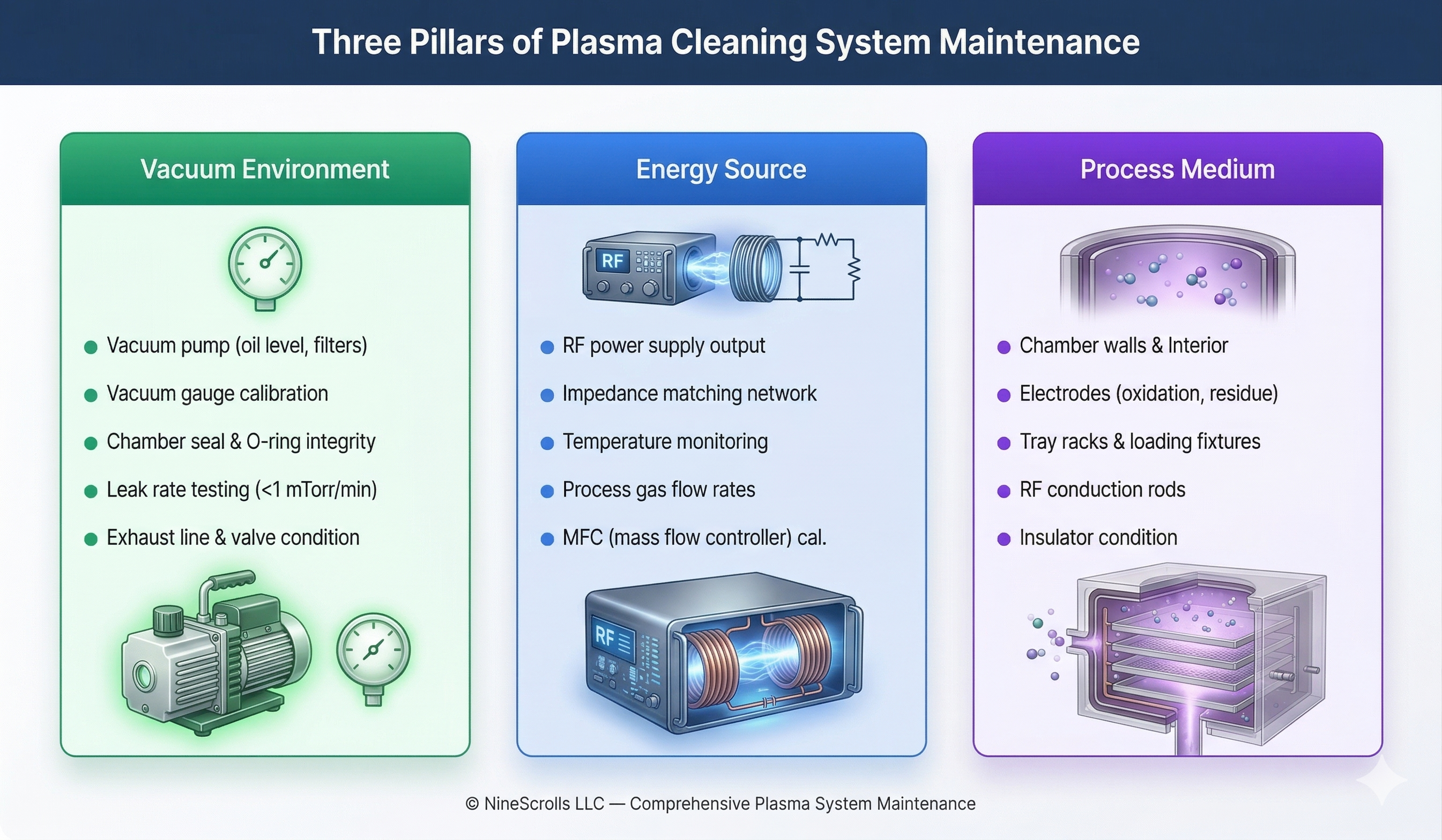
Every plasma cleaning system, regardless of manufacturer or configuration, depends on three fundamental subsystems. Understanding these “pillars” helps organize your maintenance program and ensures nothing is overlooked.
1. Vacuum Environment
The vacuum system creates and maintains the low-pressure conditions essential for plasma generation. Key components include:
- Vacuum pump — typically a rotary vane or scroll pump for plasma cleaners, requiring oil level checks, oil changes, and filter replacements
- Vacuum gauges — must be calibrated periodically to ensure accurate pressure readings
- Chamber seals and O-rings — the most common source of vacuum leaks; inspect regularly for compression set, cracking, or contamination
- Valves and plumbing — gate valves, vent valves, and gas inlet fittings must seal reliably
2. Energy Source
The RF power supply and gas delivery system provide the energy and reactive species for plasma generation:
- RF generator — output power should be verified periodically; drifting power levels directly affect cleaning performance
- Impedance matching network — ensures efficient power transfer to the plasma; component aging can increase reflected power
- Mass flow controllers (MFCs) — control process gas delivery rates; calibration drift affects process reproducibility
- Temperature monitoring — electrode and chamber temperature influence plasma chemistry and cleaning uniformity
3. Process Medium (Chamber Interior)
The chamber, electrodes, and fixturing directly contact the plasma and workpieces:
- Chamber walls — accumulate thin films of reaction byproducts that can flake and cause particle contamination
- Electrodes — develop oxide layers and hydrocarbon residue that alter plasma distribution
- Tray racks and loading fixtures — same degradation as electrodes; affect grounding and sample positioning
- RF conduction rods — contact resistance increases with oxidation, reducing power delivery efficiency
- Insulators — can develop conductive coatings from sputtered material, causing arcing
Chamber Cleaning Procedures
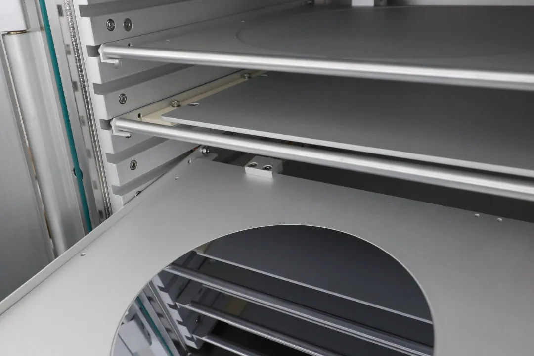
During plasma processing, most reaction byproducts are at the molecular level and are evacuated through the vacuum pump. However, larger particulate contaminants inevitably accumulate on chamber walls, the chamber floor, electrode surfaces, and tray racks. These particles can eventually detach and contaminate workpieces.
Step-by-Step Chamber Cleaning
- Power down and vent the chamber — follow your system’s standard vent procedure. Never open the chamber while under vacuum.
- Brush loose particles — use a soft, non-shedding brush (e.g., clean-room grade nylon) to dislodge particulate deposits from chamber walls, corners, and the chamber floor. Work from top to bottom.
- Vacuum extraction — use a clean-room vacuum to remove dislodged particles. Pay special attention to the chamber floor where gravity collects the most debris.
- IPA wipe-down — using lint-free polyester wipes moistened with isopropyl alcohol (IPA), thoroughly wipe all accessible interior surfaces. Replace wipes frequently — a dirty wipe redistributes contaminants rather than removing them.
- Plasma self-clean cycle — after reassembly, run a 10-minute O₂ plasma cycle at moderate power to remove any residual organic contaminants from chamber surfaces. This step is critical for restoring a clean baseline.
- Verification — run a test sample to confirm cleaning performance has returned to baseline.
⚠ Tip: Keep a chamber cleaning log. Record the date, operator, visual observations (e.g., “heavy brown residue on floor” vs. “light film on walls only”), and the post-cleaning test result. This log helps you correlate cleaning frequency with process drift and optimize your maintenance intervals.
Electrode & Tray Rack Refurbishment
Electrodes and tray racks are the most maintenance-intensive components in a plasma cleaner. Over extended use, two types of buildup occur:
- Oxide layer — aluminum electrodes naturally oxidize in the plasma environment, creating a resistive surface film that reduces RF coupling efficiency
- Hydrocarbon residue — when processing organic materials (photoresist, adhesives, biological samples), a thin polymeric film gradually accumulates on all chamber surfaces
Neither oxide layers nor hydrocarbon residue can be removed by simple IPA wiping. Chemical refurbishment is required.
Chemical Cleaning Procedure
The following procedure restores electrodes and tray racks to like-new condition. It applies to aluminum electrodes, which are the most common material in plasma cleaners.
Required Materials
- Sodium hydroxide (NaOH), reagent grade
- Sulfuric acid (H₂SO₄), reagent grade
- City (tap) water for initial rinsing
- Deionized (DI) water for final rinsing
- Chemical-resistant gloves, safety goggles, lab coat
- Well-ventilated fume hood or workspace
Step-by-Step Procedure
| Step | Action | Details | Duration |
|---|---|---|---|
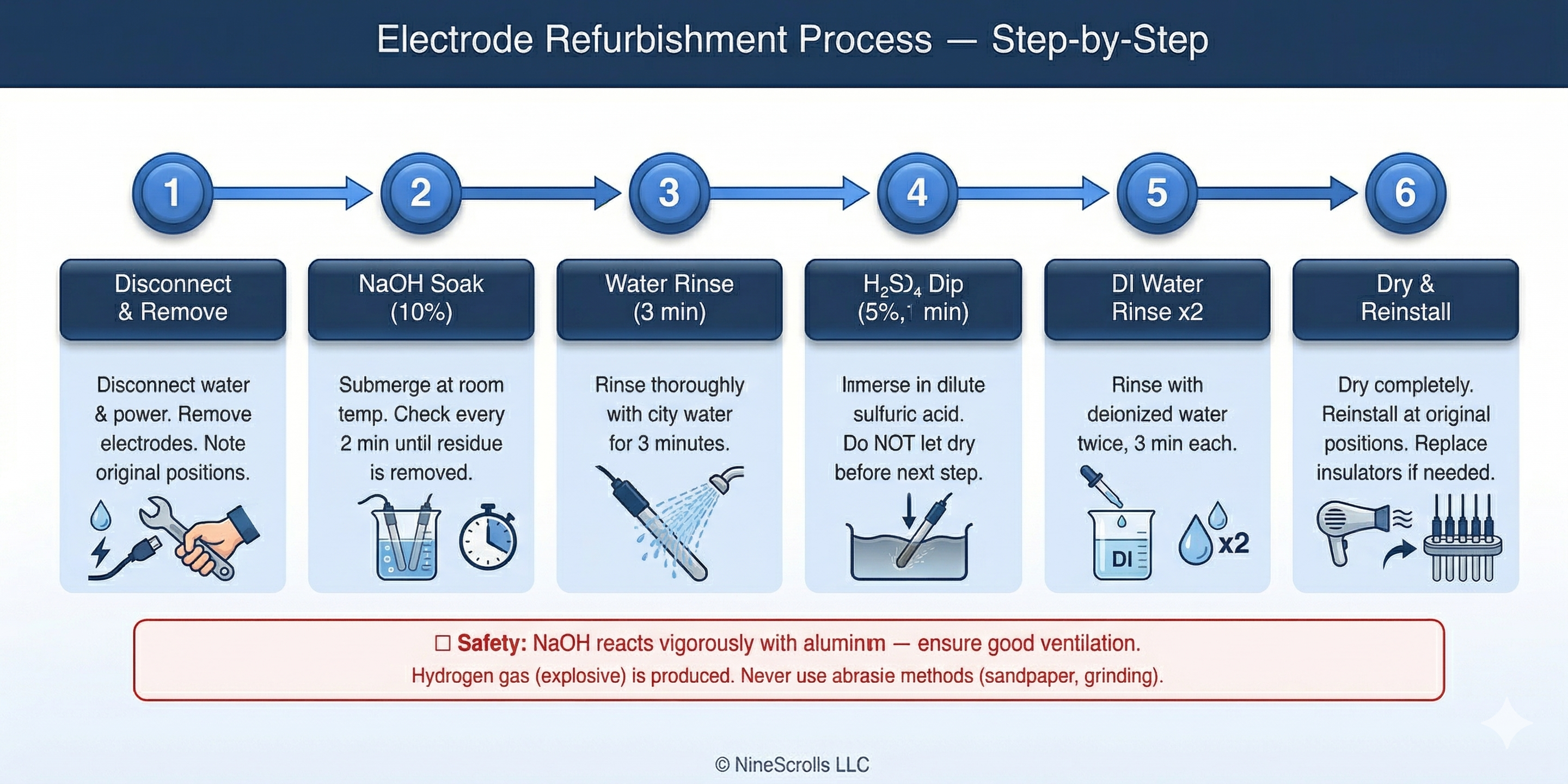
| 1 | Disconnect & remove electrodes | Disconnect water cooling and RF power connections. Remove electrodes from the vacuum chamber. Document each electrode’s position — they must be reinstalled in the same location. | — |
| 2 | NaOH soak | Prepare a 10% NaOH solution (by weight) at room temperature. Submerge electrodes completely. Check every 2 minutes until all residue is removed. Time varies with contamination level. | 4–20 min |
| 3 | City water rinse | Rinse electrodes thoroughly under running city water. | 3 min |
| 4 | H₂SO₄ dip | Prepare a 5% H₂SO₄ solution (by weight). Immerse electrodes for exactly 1 minute. Do NOT allow electrodes to dry between this step and the next — the oxide layer will re-form immediately on dry surfaces. | 1 min |
| 5 | DI water rinse (×2) | Rinse with deionized water twice, 3 minutes each rinse. This removes all acid residue and dissolved contaminants. | 6 min |
| 6 | Dry & reinstall | Dry electrodes completely (compressed nitrogen or clean dry air). Reinstall at original positions. Replace insulators if any signs of damage or conductive coating are observed. | — |
⚠ Critical Safety Warnings
- Hydrogen gas hazard: NaOH reacts vigorously with aluminum, producing hydrogen gas (H₂) which is potentially explosive. Work in a well-ventilated area — preferably under a fume hood. No open flames or ignition sources.
- Chemical burns: Both NaOH and H₂SO₄ cause severe burns. Wear chemical-resistant gloves, safety goggles, and a lab coat at all times.
- No mechanical abrasion: Never use sandpaper, grinding wheels, or abrasive blasting on electrode surfaces. Mechanical damage creates surface roughness that accelerates future contamination buildup and degrades plasma uniformity.
- Time-critical step: The H₂SO₄ dip (Step 4) must be followed immediately by DI water rinsing. If electrodes dry after the acid dip, a new oxide layer forms instantly and the acid dip must be repeated.
Vacuum System Maintenance
The vacuum system is the foundation of plasma cleaner operation. A degraded vacuum directly affects plasma ignition, process pressure stability, and base contamination levels.
Vacuum Pump Care
| Task | Frequency | Details |
|---|---|---|
| Check oil level (rotary vane pumps) | Daily | Oil should be between min/max marks on sight glass. Low oil causes overheating and poor ultimate vacuum. |
| Inspect oil color | Weekly | Fresh oil is clear/amber. Dark or milky oil indicates contamination — change immediately. |
| Change pump oil | Semi-annually (or when discolored) | Use manufacturer-specified oil grade. Drain while warm for best results. Flush with fresh oil if heavily contaminated. |
| Replace exhaust filters | Semi-annually | Clogged exhaust filters increase back-pressure and reduce pumping speed. Replace on schedule. |
| Check tip seals (scroll pumps) | Annually | Scroll pump tip seals wear gradually. Degraded seals manifest as higher base pressure and longer pump-down times. |
Leak Testing
Vacuum leaks are insidious — a small leak may not prevent plasma ignition but will introduce atmospheric contamination (water vapor, nitrogen, oxygen) that degrades process control. Perform a rate-of-rise leak test at least semi-annually:
- Pump the chamber to base pressure and record the reading.
- Close the vacuum valve to isolate the chamber from the pump.
- Monitor pressure rise over 5–10 minutes.
- A leak rate below 1 mTorr/min is acceptable for most plasma cleaning applications.
- If the leak rate exceeds specification, systematically check door seals, feedthrough O-rings, gas line fittings, and viewport seals.
RF Power Supply & Gas System Checks
RF Power Verification
Over time, RF generator output can drift. Periodic verification ensures your process recipes deliver the intended power:
- Forward/reflected power check — at your standard process conditions, verify that reflected power is below 5% of forward power. Higher reflected power indicates matching network issues or chamber condition changes.
- Matching network inspection — the automatic matching network contains variable capacitors and inductors. Annual inspection for signs of arcing, discoloration, or mechanical wear on tuning elements is recommended.
- Cable and connector integrity — RF cables and connectors degrade over time. Check for secure connections, shield integrity, and signs of heating (discoloration at connectors).
Gas System Checks
- Leak test gas lines — use an electronic leak detector or apply leak-detection solution to all fittings from the gas cylinder to the chamber inlet. Even minor gas leaks waste expensive process gases and can introduce contaminants.
- MFC calibration — mass flow controllers should be calibrated annually. Drifted MFCs cause recipe non-reproducibility that is difficult to diagnose.
- Regulator inspection — check delivery pressure regulators for creep (gradually rising delivery pressure with the valve closed). Replace diaphragms as needed.
Preventive Maintenance Schedule
The following schedule provides a comprehensive framework. Adjust frequencies based on your specific usage intensity, process chemistry, and environmental conditions.
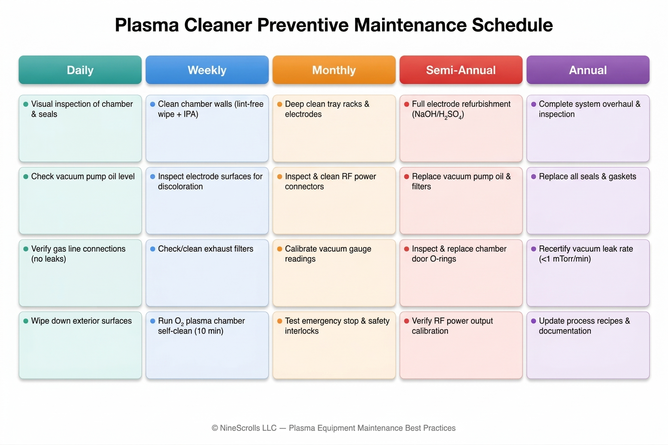
Daily Checks (5 minutes)
- Visual inspection of chamber door seal — no debris, cracks, or compression set
- Vacuum pump oil level (rotary vane pumps)
- Gas line connections — verify no audible leaks
- Exterior surface wipe-down to prevent dust ingression
Weekly Maintenance (30–60 minutes)
- Chamber interior wipe-down with lint-free wipes and IPA
- Visual inspection of electrode surfaces for discoloration or residue buildup
- Exhaust filter condition check
- O₂ plasma self-clean cycle (10 minutes at moderate power)
Monthly Maintenance (1–2 hours)
- Deep clean tray racks and electrode surfaces (IPA + lint-free wipes)
- Inspect and clean RF power connectors and conduction rods
- Calibrate vacuum gauge against a reference gauge
- Test emergency stop button and safety interlocks
- Review maintenance log for trends
Semi-Annual Maintenance (4–8 hours)
- Full electrode and tray rack chemical refurbishment (NaOH/H₂SO₄ procedure)
- Vacuum pump oil change and exhaust filter replacement
- Chamber door O-ring inspection and replacement if needed
- Rate-of-rise vacuum leak test
- RF power output verification
Annual Maintenance (1–2 days)
- Complete system inspection and overhaul
- Replace all seals and gaskets
- Vacuum leak rate recertification (< 1 mTorr/min)
- Matching network internal inspection
- MFC calibration verification
- Update process recipes and maintenance documentation
Troubleshooting Common Issues
Many plasma cleaner performance problems trace back to maintenance-related root causes. The table below helps connect symptoms to their most likely causes.
| Symptom | Possible Cause | Maintenance Action |
|---|---|---|
| Plasma won’t ignite | Vacuum leak; contaminated electrode; broken gas line | Leak test; clean/refurbish electrodes; check gas connections |
| Unstable/flickering plasma | Dirty electrodes; poor RF contact; incorrect pressure | Clean electrodes and RF connectors; verify vacuum gauge calibration |
| Declining cleaning performance | Electrode oxide buildup; contaminated chamber; drifted MFC | Refurbish electrodes; deep clean chamber; calibrate MFCs |
| Long pump-down time | Worn O-ring; low pump oil; contaminated pump oil | Replace O-rings; check/change pump oil |
| High reflected RF power | Matching network drift; damaged RF cable; arcing in chamber | Inspect matching network; check cables; clean chamber for arc sources |
| Particle contamination on samples | Flaking deposits on chamber walls; degraded electrode surface | Full chamber clean; electrode refurbishment |
| Unusual odor from exhaust | Contaminated pump oil; clogged exhaust filter | Change pump oil; replace exhaust filter |
Frequently Asked Questions
How often should I refurbish my plasma cleaner electrodes?
For typical lab usage (4–8 hours/day), semi-annual refurbishment is a good starting point. High-volume production environments or processes involving heavy organic loading (photoresist stripping, adhesive removal) may require quarterly refurbishment. Monitor your process results — if you notice declining cleaning uniformity or increasing variability, it’s time to refurbish regardless of the calendar.
Can I use sandpaper or abrasive pads to clean electrodes?
No. Mechanical abrasion creates surface micro-roughness that accelerates future contaminant adhesion, alters the electrode’s electrical properties, and reduces its usable lifetime. Always use the chemical cleaning procedure (NaOH soak → water rinse → H₂SO₄ dip → DI water rinse). The chemical process removes deposits without damaging the underlying aluminum surface.
What vacuum leak rate is acceptable for a plasma cleaner?
For most plasma cleaning applications, a rate-of-rise leak rate below 1 mTorr/min is acceptable. More sensitive processes (e.g., surface activation before bonding, or processes using expensive specialty gases) may require tighter leak rates of 0.5 mTorr/min or below. If your leak rate exceeds specification, systematically check the door seal, feedthrough O-rings, gas line fittings, and viewport seals.
Why does my plasma cleaner performance degrade even though I clean the chamber regularly?
Chamber cleaning (IPA wipe-down) removes loose particles and surface films but does not address oxide buildup on electrodes or hydrocarbon polymerization on electrode/tray rack surfaces. These deeper deposits require the chemical refurbishment process. Additionally, gradual vacuum degradation (worn O-rings, pump oil contamination), RF power drift, and MFC calibration drift can all cause performance changes that chamber cleaning alone cannot fix. A comprehensive maintenance program must address all three pillars: vacuum environment, energy source, and process medium.
How long does the electrode refurbishment process take?
The active hands-on time is approximately 30–60 minutes per set of electrodes, depending on the level of contamination. The NaOH soak step is the most variable — lightly contaminated electrodes may need only 4–6 minutes, while heavily fouled ones can take 15–20 minutes. Allow an additional 1–2 hours for electrode drying and system reassembly. Plan the refurbishment for a scheduled maintenance window to avoid impacting production.
NineScrolls Plasma Cleaning Solutions
Our plasma cleaners are engineered for easy maintenance with quick-release electrodes, accessible chamber designs, and comprehensive maintenance documentation.