Why Plasma is Non-Uniform in Etch Chambers and How to Solve It
By NineScrolls Engineering · 2025-08-19 · 17 min read · Materials Science
Target Readers: Semiconductor process engineers, equipment engineers, R&D scientists, and technical staff working with plasma etching systems.
TL;DR Summary
Plasma non-uniformity in etch chambers is a common issue affecting process reproducibility and device yield. This guide explains the root causes, measurement methods, and practical solutions for achieving uniform plasma distribution in your etching processes.
1) Understanding Plasma Uniformity
1.1 What is Plasma Uniformity?
Plasma uniformity refers to the consistency of plasma density, temperature, and reactive species distribution across the substrate surface. Non-uniform plasma leads to inconsistent etching rates and poor device performance.
1.2 Why Plasma Uniformity Matters
- Process Reproducibility: Uniform plasma ensures consistent etch rates across the wafer
- Device Yield: Non-uniformity can cause device failures and reduced yield
- Cost Efficiency: Uniform processes reduce material waste and rework
- Quality Control: Consistent results enable better quality control
2) Common Causes of Plasma Non-Uniformity
2.1 Equipment-Related Factors
- RF Power Distribution: Uneven power coupling to the plasma
- Gas Flow Patterns: Non-uniform gas distribution in the chamber
- Chamber Geometry: Asymmetric chamber design or wear
- Electrode Configuration: Misaligned or damaged electrodes
- Magnetic Field Effects: Unintended magnetic field interference
2.2 Process-Related Factors
- Pressure Variations: Non-uniform pressure distribution
- Temperature Gradients: Substrate temperature variations
- Gas Chemistry: Inconsistent reactive species generation
- Chamber Conditioning: Poor chamber wall conditioning
- Substrate Loading Effects: Pattern-dependent loading effects
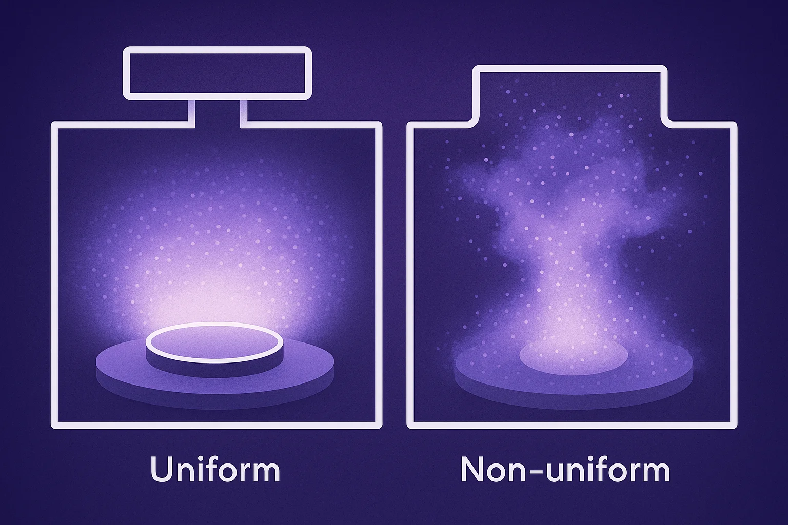
Figure 1: Plasma Uniformity Analysis - Showing uniform vs non-uniform plasma distribution patterns
3) Gas Flow vs. Temperature: Diagnosing the Root Cause of Etch Rate Non-Uniformity
When researchers first observe non-uniform etch rates across a sample, the instinct is often to adjust power or pressure. But in most laboratory plasma systems, the real culprits are more specific: uneven gas flow distribution and substrate temperature gradients. These two mechanisms are frequently conflated, yet they produce distinct symptoms—and demand different engineering responses.
Understanding which one dominates your process is the first step toward a reliable fix.
3.1 How Gas Flow Non-Uniformity Affects Etch Rate
Plasma etching is a surface reaction driven by the local concentration of reactive radicals. When gas enters the chamber unevenly, the radical density is higher near the inlet and depleted toward the exhaust side. The result is a spatially dependent etch rate that follows the gas concentration gradient, not the plasma density.
In a typical downstream or parallel-plate plasma cleaner operating at low-to-medium pressure (50–500 mTorr), gas flow non-uniformity tends to produce:
- Center-to-edge etch rate gradients — often called the "bullseye" pattern, where the etch rate is either fastest at the center (center-injection geometry) or fastest at the perimeter (edge-injection geometry)
- Side-to-side asymmetry — when the pump port is offset from the gas inlet, a directional gradient appears across the sample
- Pressure-sensitive behavior — the non-uniformity worsens at lower flow rates, where radical depletion along the flow path becomes more pronounced
- Fast response to flow rate changes — adjusting total flow or inlet geometry shows an effect within the same process run
Key diagnostic marker: if your etch rate non-uniformity changes significantly when you vary gas flow rate or chamber pressure, but not when you vary RF power alone, gas flow distribution is the dominant cause.
3.2 How Temperature Gradients Affect Etch Rate
Most plasma etch reactions are thermally activated, following Arrhenius kinetics. Even modest temperature differences across a substrate—on the order of 5–20°C—can produce etch rate variations of 10–30% for common processes involving oxygen, fluorine, or chlorine chemistries.
In laboratory plasma systems without active substrate heating, temperature non-uniformity arises from:
- RF-induced heating of the sample — areas exposed to higher ion flux heat up faster than shielded areas
- Poor thermal contact with the sample stage — only the contacted area is effectively cooled, leaving overhanging sample edges hotter
- Chamber wall temperature asymmetry — chambers that have just been cleaned or powered on show pronounced thermal gradients until equilibrium is reached
- Accumulated run-to-run thermal drift — etch rate shifts gradually over the first several runs until the chamber reaches thermal steady state
Temperature-driven non-uniformity produces a distinct signature:
- Etch rate drifts over time within a single run, becoming more uniform as the substrate equilibrates
- Radial pattern correlated with sample contact geometry, not gas inlet position
- Low sensitivity to flow rate changes, but strong sensitivity to RF power level and process duration
- Run-to-run variability that stabilizes after a chamber warm-up run
3.3 Separating the Contributions: A Practical Diagnostic Approach
In practice, gas flow and temperature effects overlap. A pragmatic diagnostic approach for laboratory plasma systems:
Step 1 — Thermal isolation test: Run the same process recipe twice: once immediately after a 10-minute "dummy" warm-up run, and once on a cold chamber. If etch rate and uniformity differ significantly between the two runs, thermal drift is a major contributor.
Step 2 — Flow rate sensitivity test: Hold RF power constant. Run at 50%, 75%, and 100% of your target flow rate. If uniformity (center-to-edge ratio) changes noticeably with flow rate, gas distribution is a major contributor.
Step 3 — Rotate the sample: If the non-uniformity pattern rotates with the sample but not with the chamber geometry, the cause is local to the substrate (thermal contact, loading position). If the pattern stays fixed relative to the chamber regardless of sample orientation, the cause is the chamber geometry (gas inlet position, pump port asymmetry).
3.4 Matching the Fix to the Root Cause
| Root Cause | Practical Solutions |
|---|---|
| Gas flow non-uniformity | Use a showerhead-type gas inlet; increase total flow rate to reduce radical depletion along the path; ensure pump port is directly opposite the gas inlet for symmetric evacuation |
| Temperature gradient | Allow thermal equilibration with a warm-up run before process samples; use a sample stage with active temperature control; clamp samples flat to maximize thermal contact |
| Both present | Address gas flow first (faster to control), then characterize residual non-uniformity under thermally stable conditions |
For research-grade plasma etching systems designed for university and institutional labs—such as the ICP-RIE and RIE systems from NineScrolls—chamber geometry is engineered for symmetric gas distribution, and the sample stage supports temperature-controlled operation across a defined process window. This reduces the burden on researchers to compensate for hardware-induced non-uniformity through process recipe adjustments alone.
3.5 Understanding Uniformity Specifications
When evaluating plasma systems, uniformity is typically expressed as:
Uniformity (%) = (Rmax − Rmin) / (2 × Ravg) × 100
where R is the etch rate measured at multiple points across the sample. A specification of ±5% uniformity means the etch rate varies no more than 5% from the average across the measurement zone—typically excluding a defined edge exclusion zone of 3–5 mm.
This number is always process-condition-specific. A system may achieve ±3% uniformity under the vendor's benchmark recipe (often O₂ plasma at a specific power and pressure) but show wider variation under your actual process conditions. When comparing systems, always ask for uniformity data under conditions close to your intended application.
4) Measurement and Characterization Methods
4.1 Optical Emission Spectroscopy (OES)
- Principle: Measures light emission from excited species
- Advantages: Non-intrusive, real-time monitoring
- Limitations: Line-of-sight measurement only
- Applications: Plasma density and temperature mapping
4.2 Langmuir Probe Measurements
- Principle: Direct measurement of plasma parameters
- Advantages: High spatial resolution, accurate data
- Limitations: Intrusive, requires probe insertion
- Applications: Electron density and temperature profiles
4.3 Etch Rate Mapping
- Principle: Measures actual etch rate across the wafer
- Advantages: Direct process result measurement
- Limitations: Destructive, post-process analysis
- Applications: Process uniformity validation
5) Solutions for Plasma Uniformity Issues
5.1 Equipment Optimization
5.1.1 RF Power Distribution
- Multi-Zone RF Systems: Independent control of different chamber zones
- Impedance Matching: Optimize RF coupling efficiency
- Frequency Tuning: Adjust RF frequency for better uniformity
- Power Ramping: Gradual power increase to stabilize plasma
5.1.2 Gas Distribution Systems
- Multi-Port Gas Injection: Multiple gas inlets for uniform distribution
- Gas Flow Optimization: Adjust flow rates and patterns
- Showerhead Design: Optimize showerhead geometry and hole patterns
- Gas Mixing: Ensure proper mixing before injection
5.2 Process Optimization
5.2.1 Pressure and Temperature Control
- Pressure Optimization: Find optimal pressure for uniformity
- Temperature Uniformity: Ensure uniform substrate heating
- Thermal Management: Control chamber wall temperatures
- Gas Heating: Pre-heat process gases if needed
5.2.2 Chamber Conditioning
- Wall Passivation: Proper chamber wall conditioning
- Cleaning Procedures: Regular chamber cleaning
- Seasoning: Chamber seasoning with process gases
- Maintenance Schedule: Regular preventive maintenance
6) Advanced Solutions and Technologies
6.1 Magnetic Field Control
- Magnetic Confinement: Use magnetic fields to control plasma distribution
- Magnetic Shielding: Shield unwanted magnetic interference
- Magnetic Field Mapping: Characterize and optimize magnetic field distribution
6.2 Adaptive Control Systems
- Real-Time Monitoring: Continuous plasma uniformity monitoring
- Feedback Control: Automatic adjustment of process parameters
- Machine Learning: AI-based optimization algorithms
- Predictive Maintenance: Prevent uniformity issues before they occur
7) Troubleshooting Guide
| Symptom | Possible Cause | Solution |
|---|---|---|
| Center-to-Edge Non-Uniformity | Gas flow patterns, RF coupling | Optimize gas distribution, adjust RF power |
| Radial Non-Uniformity | Chamber geometry, electrode alignment | Check chamber symmetry, realign electrodes |
| Random Non-Uniformity | Contamination, poor conditioning | Clean chamber, improve conditioning |
| Time-Dependent Non-Uniformity | Chamber aging, temperature drift | Monitor chamber condition, control temperature |
8) NineScrolls Plasma Etching Solutions
NineScrolls offers advanced plasma etching systems with built-in uniformity control features:
8.1 Advanced Control Features
- Multi-Zone RF Control: Independent control of different chamber zones
- Real-Time Monitoring: Continuous plasma uniformity monitoring
- Adaptive Control: Automatic adjustment for optimal uniformity
- Advanced Diagnostics: Comprehensive plasma characterization tools
8.2 Process Optimization Support
- Technical Consultation: Expert guidance on uniformity optimization
- Process Development: Custom process development services
- Training Programs: Comprehensive operator training
- Maintenance Support: Preventive maintenance and troubleshooting
9) Best Practices for Plasma Uniformity
9.1 Equipment Setup
- Regular equipment calibration and maintenance
- Proper chamber conditioning procedures
- Optimized gas flow and pressure settings
- Consistent substrate loading and positioning
9.2 Process Control
- Monitor key process parameters continuously
- Implement statistical process control (SPC)
- Regular uniformity testing and validation
- Document and track process changes
10) Conclusion
Plasma non-uniformity is a complex issue that requires systematic analysis and optimization. By understanding the root causes and implementing appropriate solutions, you can achieve consistent, high-quality etching processes. Regular monitoring and preventive maintenance are key to maintaining plasma uniformity over time.
Call-to-Action
- Experiencing plasma uniformity issues? Contact our technical team for consultation.
- Interested in our advanced plasma etching systems? Explore our product range.
- Need process optimization support? Our process engineers are available for technical discussions.
Contact:
Plasma Etching Systems: https://www.ninescrolls.com/products
Technical Support: https://www.ninescrolls.com/contact
Email: info@ninescrolls.com
References
- Lee, C. & Lieberman, M. A. "Global model of Ar, O₂, Cl₂, and Ar/O₂ high-density plasma discharges." Journal of Vacuum Science & Technology A, 13(2), 368–380 (1995). doi:10.1116/1.579366
- Kushner, M. J. "Hybrid modelling of low temperature plasmas for fundamental investigations and equipment design." Journal of Physics D: Applied Physics, 42(19), 194013 (2009). doi:10.1088/0022-3727/42/19/194013
- Lieberman, M. A. & Lichtenberg, A. J. Principles of Plasma Discharges and Materials Processing, 2nd ed. Wiley-Interscience (2005). ISBN 978-0471720010.